![]()
![]()

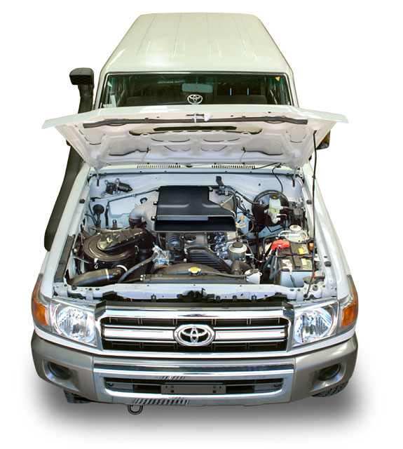
Safari Intercooler System SCHZJ70W
| Parts List | ||||||||||||||||||||||||||||||||||||||||||||||||||||||||||||||||||||||||||||||||||||||||||
|
||||||||||||||||||||||||||||||||||||||||||||||||||||||||||||||||||||||||||||||||||||||||||
| Installation Guide | ||||||||||||||||||||||||||||||||||||||||||||||||||||||||||||||||||||||||||||||||||||||||||
Special Tools
|
||||||||||||||||||||||||||||||||||||||||||||||||||||||||||||||||||||||||||||||||||||||||||
| 1 | Remove the following items:
.Discard the intake duct and turbocharger outlet hose |
 |
||||||||||||||||||||||||||||||||||||||||||||||||||||||||||||||||||||||||||||||||||||||||
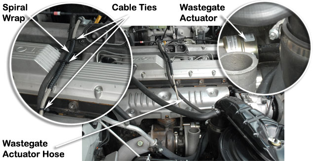
| 2 | Install the spiral wrap (Item 7) to the turbocharger oil supply hose.
Install spring clamps the new wastegate actuator hose (Item 6) and install the hose to the wastegate actuator. Route the actuator hose as shown and support with three cable ties (Item 8) along the turbocharger oil supply hose. |
 |
||||||||||||||||||||||||||||||||||||||||||||||||||||||||||||||||||||||||||||||||||||||||
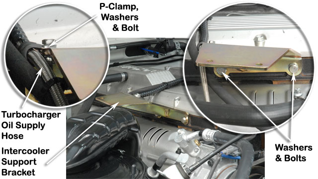
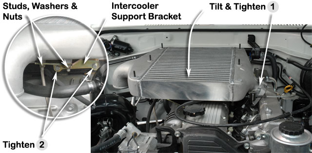
| 3 | Install the intercooler support bracket (Item 5) to the cylinder head and retain with two hex bolts (Item 14), star washers (Item 13) and flat washers (Item 12).
Do not tighten fully yet. Install the hose support P-clamp to the turbocharger oil supply hose and fasten to the intercooler support bracket (Item 5) with the bolt, washers and nut retained previously. |
 |
||||||||||||||||||||||||||||||||||||||||||||||||||||||||||||||||||||||||||||||||||||||||
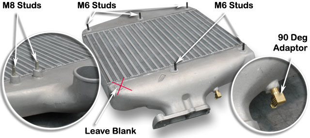
| 4 | Apply Loctite 243 to the five M6 studs (Item 15) and install into to the intercooler assembly (Item 4) in the positions shown.
Apply hydraulic sealant to the 90 deg adaptor (Item 9) and install into to the intercooler assembly (Item 4) in the orientation shown. Apply Loctite 243 to the two M8 studs (Item 10) and install into to the intercooler assembly (Item 4). |
 |
||||||||||||||||||||||||||||||||||||||||||||||||||||||||||||||||||||||||||||||||||||||||
| 5 | Install the intercooler assembly to the intake manifold using the original intake manifold retaining bolts - but do not tighten fully yet.
Ensure that the M8 studs (Item 10) installed previously are located in the intercooler mounting bracket holes. Tilt the front of the intercooler assembly downwards and tighten the three original intake manifold retaining bolts. Install the two M8 washers (Item 12) and M8 nuts (Item 11) to the M8 studs and tighten fully. Tighten the two M8 intercooler mounting bracket bolts (Item 14) previously installed to cylinder head. |
 |
||||||||||||||||||||||||||||||||||||||||||||||||||||||||||||||||||||||||||||||||||||||||
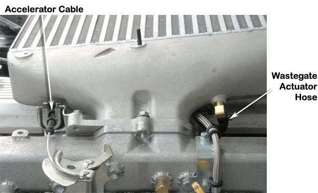
| 6 | Install the wastegate actuator hose (Item 6) to the 90 degree adaptor (Item 9).
Install the accelerator cable to the flange on the intercooler assembly and retain with the original bolts. Check for full throttle and adjust accelerator cable as required. |
 |
||||||||||||||||||||||||||||||||||||||||||||||||||||||||||||||||||||||||||||||||||||||||
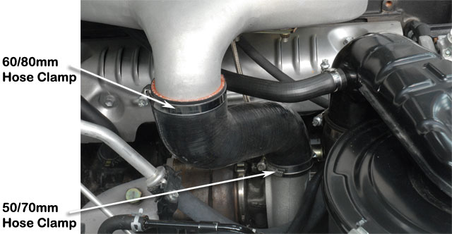
| 7 | Install the 50/70mm hose clamp (Item 2) to the lower end and the 60/80mm hose clamp (Item 3) to the upper end of the turbocharger compressor discharge hose (Item 1)
Install the hose (Item 1) between the turbocharger and intercooler intake. Ensure that each hose clamp is square to the hose and tighten. |
 |
||||||||||||||||||||||||||||||||||||||||||||||||||||||||||||||||||||||||||||||||||||||||
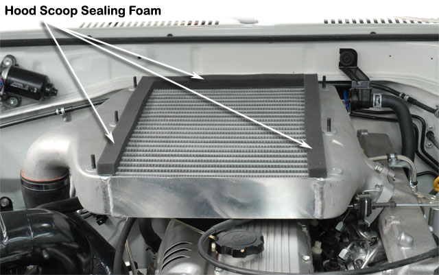
| 8 | The sealing foam strips (Item 18) are supplied in two lengths. One short length for the rear and two longer lengths for sides.
Peel back the adhesive backing from the sealing foam strip (Item 18) and install the sealing foam strip to the intercooler LHS, Rear and RHS of the top face as shown. |
 |
||||||||||||||||||||||||||||||||||||||||||||||||||||||||||||||||||||||||||||||||||||||||
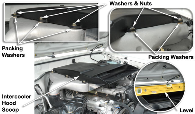
| 9 | To begin with, place three M6 body washers (Item 16) to the rear most M6 intercooler studs (Item 15), two washers to the two centre studs and one washer to the RHS front stud.
Install the hood scoop and check for level relative to the vehicle body. Use washers (Item 16) as required to ensure that the hood scoop is perfectly level. Secure the hood scoop to the intercooler assembly with M6 washers (Item 16) and M6 nyloc nuts (Item 17). |
 |
||||||||||||||||||||||||||||||||||||||||||||||||||||||||||||||||||||||||||||||||||||||||
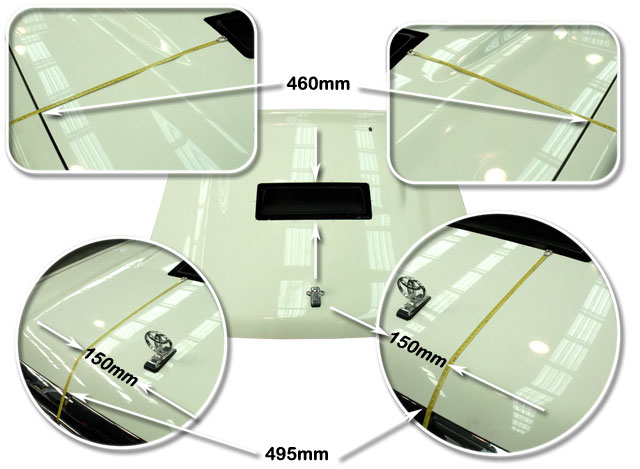
| 10 | Mark the hood panel mounting bolt positions for future reference and remove the hood panel from the vehicle. Place the hood panel on a protective mat to avoid scratches.
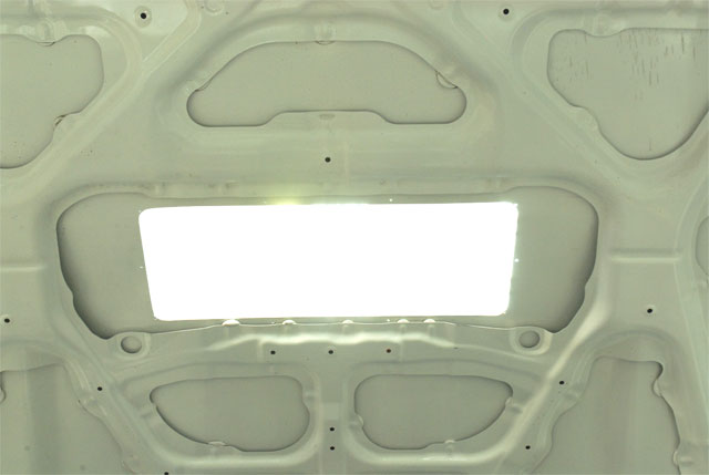
Measure the hood scoop opening with a flexible tape measure as shown and mark with a felt tip pen. Use a reciprocating body saw to cut the hood scoop opening. Check the hood scoop opening with the aperture surround trim piece (Item 20) and trim hole if required for neat fit. |
 |
||||||||||||||||||||||||||||||||||||||||||||||||||||||||||||||||||||||||||||||||||||||||
| 11 | Deburr and paint hood panel.
Install the hood panel back onto the vehicle and adjust to the previous markings for good panel fit. |
 |
||||||||||||||||||||||||||||||||||||||||||||||||||||||||||||||||||||||||||||||||||||||||
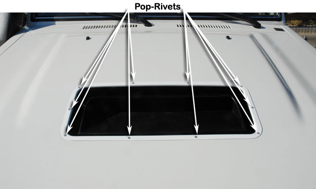
| 12 | Close the hood panel and install the aperture surround trim piece (Item 20). Adjust the position for best fit and at one corner, drill one mounting hole position with a 3.3mm diameter drill bit. Insert a pop rivet (Item 21) into the hole and then repeat the process at the opposite corner.
Continue to drill and insert pop-rivets. When all ten pop rivets (Item 21) are inserted, fasten with a pop rivet gun. |
 |
||||||||||||||||||||||||||||||||||||||||||||||||||||||||||||||||||||||||||||||||||||||||