![]()
![]()

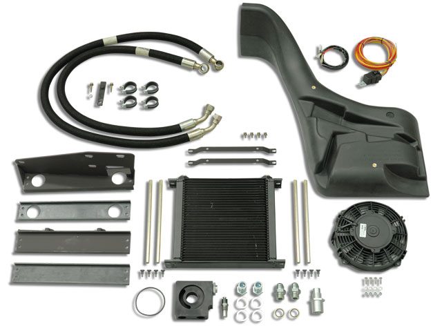
Safari Engine Oil Cooler System SOHZJ70W
| Parts List | ||||||||||||||||||||||||||||||||||||||||||||||||||||||||||||||||||||||||||||||||||||||||||||||||||||||||||||||||||||||||||||||||||||||||||||||||||||||||||||||
|
||||||||||||||||||||||||||||||||||||||||||||||||||||||||||||||||||||||||||||||||||||||||||||||||||||||||||||||||||||||||||||||||||||||||||||||||||||||||||||||
| Installation Guide | ||||||||||||||||||||||||||||||||||||||||||||||||||||||||||||||||||||||||||||||||||||||||||||||||||||||||||||||||||||||||||||||||||||||||||||||||||||||||||||||
Special Tools
CAUTION: Do not use thread tape or similar on hydraulic fittings. |
||||||||||||||||||||||||||||||||||||||||||||||||||||||||||||||||||||||||||||||||||||||||||||||||||||||||||||||||||||||||||||||||||||||||||||||||||||||||||||||
| 1 | Disconnect the negative terminal from the battery. | |||||||||||||||||||||||||||||||||||||||||||||||||||||||||||||||||||||||||||||||||||||||||||||||||||||||||||||||||||||||||||||||||||||||||||||||||||||||||||||
| 2 | Remove the air cleaner assembly in accordance with the factory service manual. | |||||||||||||||||||||||||||||||||||||||||||||||||||||||||||||||||||||||||||||||||||||||||||||||||||||||||||||||||||||||||||||||||||||||||||||||||||||||||||||
| 3 | Disconnect all wiring from the alternator. | |||||||||||||||||||||||||||||||||||||||||||||||||||||||||||||||||||||||||||||||||||||||||||||||||||||||||||||||||||||||||||||||||||||||||||||||||||||||||||||
| 4 | Remove the three steering damper bracket retaining bolts from the RHS chassis rail. | 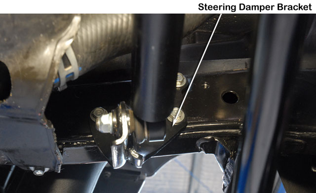 |
||||||||||||||||||||||||||||||||||||||||||||||||||||||||||||||||||||||||||||||||||||||||||||||||||||||||||||||||||||||||||||||||||||||||||||||||||||||||||||
| 5 | Unclip the RHS rubber inner guard liner. | 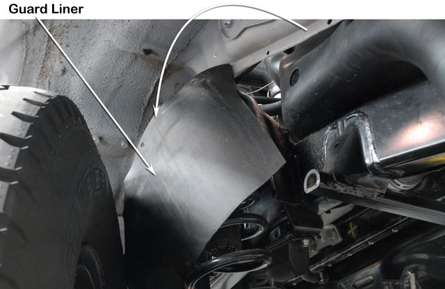 |
||||||||||||||||||||||||||||||||||||||||||||||||||||||||||||||||||||||||||||||||||||||||||||||||||||||||||||||||||||||||||||||||||||||||||||||||||||||||||||
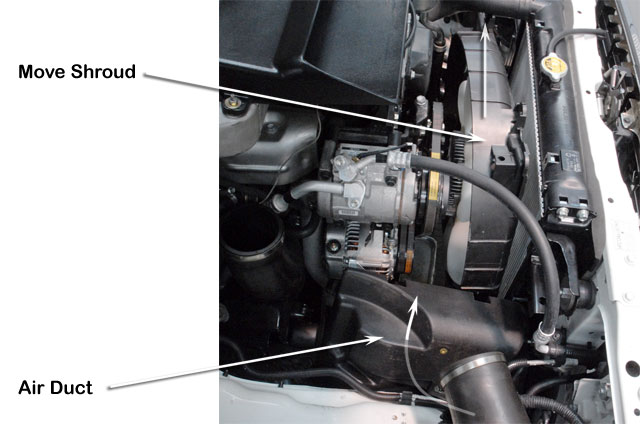
| 6 | Unbolt the radiator fan shroud from the radiator (do not remove shroud).
Move the fan shroud towards the LHS of the vehicle. Install the air duct (Item 30) from underneath the vehicle. Note that this may require a degree of force on the duct. |
 |
||||||||||||||||||||||||||||||||||||||||||||||||||||||||||||||||||||||||||||||||||||||||||||||||||||||||||||||||||||||||||||||||||||||||||||||||||||||||||||
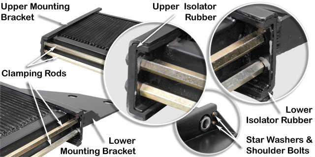
| 7 | Install the upper and lower isolator rubbers (items 5 & 6) to the upper and lower oil cooler core mounting brackets (Items 2 & 3).
Install the four bracket clamping rods (Item 4) to the oil cooler. Install the upper and lower mounting brackets (Items 2 & 3) to the oil cooler (Item 1) and retain with star washers (Item 8) and M5 shoulder bolts (Item 7). Evenly tighten all eight shoulder bolts (Item 7). |
 |
||||||||||||||||||||||||||||||||||||||||||||||||||||||||||||||||||||||||||||||||||||||||||||||||||||||||||||||||||||||||||||||||||||||||||||||||||||||||||||
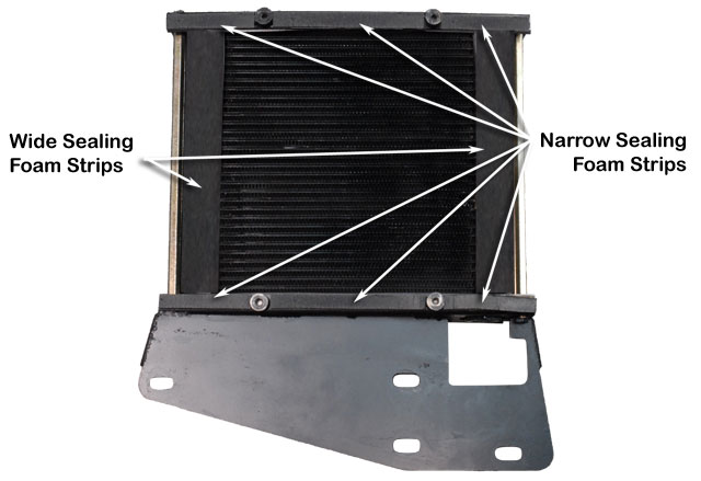
| 8 | Measure and cut the wide and narrow sealing foam strips (Item 35 & 36) to length as shown.
Remove the adhesive backing from the wide oil cooler sealing foam strips (Item 35) and install onto the oil cooler core (Item 1) as shown. Remove the adhesive backing from the narrow oil cooler sealing foam strips (Item 36) and install onto the oil cooler core mounting brackets (Items 2 & 3) as shown. |
 |
||||||||||||||||||||||||||||||||||||||||||||||||||||||||||||||||||||||||||||||||||||||||||||||||||||||||||||||||||||||||||||||||||||||||||||||||||||||||||||
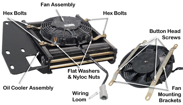
| 9 | Install the fan mounting brackets (Item 23) to the fan assembly (Item 25) in the orientation relative to the wiring loom as shown.
Retain with M5 button head screws (Item 26), flat washers (Item 28) and nyloc nuts (Item 27). Do not tighen fully yet. Install the fan assembly onto the oil cooler assembly and move brackets (Item 23) to align the mounting holes to the upper and lower bracket bosses. When correctly aligned, carefully lift the fan assembly and tighten the M5 button head screws (Item 26) fully. Install the fan assembly to the oil cooler assembly and retain with four M6 SEMs bolts (Item 24). Use a sharp blade to trim a notch in the foam strip for the fan wiring loom. |
 |
||||||||||||||||||||||||||||||||||||||||||||||||||||||||||||||||||||||||||||||||||||||||||||||||||||||||||||||||||||||||||||||||||||||||||||||||||||||||||||
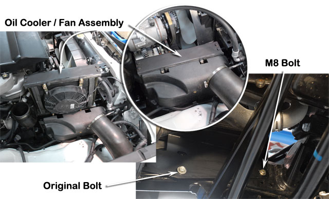
| 10 | Install the oil cooler/fan assembly carefully from above taking care to protect the oil cooler core fins from damage.
Secure to the RHS chassis rail with one steering damper bracket bolt and one M8 SEMs bolt (Item 19). |
 |
||||||||||||||||||||||||||||||||||||||||||||||||||||||||||||||||||||||||||||||||||||||||||||||||||||||||||||||||||||||||||||||||||||||||||||||||||||||||||||
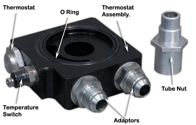
| 11 | Secure the oil filter/thermostat block (Item 15) into a vice with soft jaws.
Place a small amount of hydraulic sealant to the threads of the temperature switch (Item 29) and install into the block. Repeat the process for the two aluminium washers (Item 11) and M22 adaptors (Item 14). Place a small amount of rubber grease to the O ring (Item 16) and install the O ring into the ring groove in the block as shown. |
 |
||||||||||||||||||||||||||||||||||||||||||||||||||||||||||||||||||||||||||||||||||||||||||||||||||||||||||||||||||||||||||||||||||||||||||||||||||||||||||||
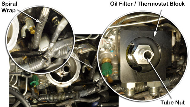
| 12 | Remove the engine oil filter from the engine block.
Install the 150mm spiral wrap (Item 37) over the turbocharger oil supply hose as shown. Install the oil filter/thermostat block (Item 15) to the oil filter location on the engine block. Note orientation. Secure the block in place with the tube nut. (Item 15) and tighten to 30 ft.lb torque. Reinstall oil filter. |
 |
||||||||||||||||||||||||||||||||||||||||||||||||||||||||||||||||||||||||||||||||||||||||||||||||||||||||||||||||||||||||||||||||||||||||||||||||||||||||||||
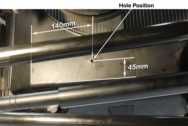
| 13 | Reinstall the radiator fan shroud.
Mark the hole position on the radiator fan shroud as shown. Drill a 7mm hole in the marked position. |
 |
||||||||||||||||||||||||||||||||||||||||||||||||||||||||||||||||||||||||||||||||||||||||||||||||||||||||||||||||||||||||||||||||||||||||||||||||||||||||||||
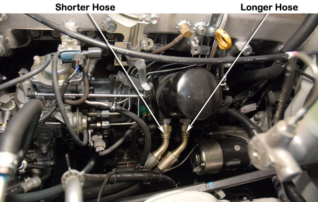
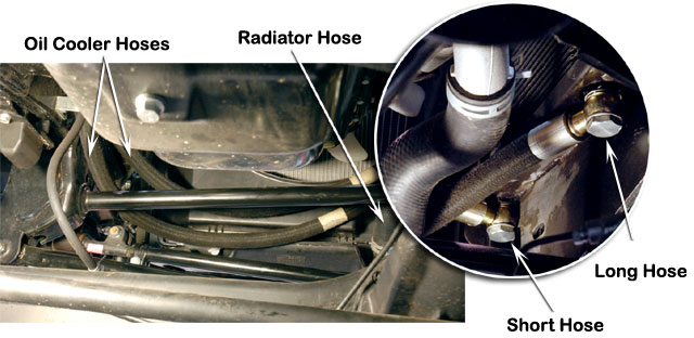
| 14 | Install the longer hose assembly (Item 12) to the rearward adaptor (Item 14) and the shorter hose (Item 13) to the forward adaptor (Item 14) of the oil filter/thermostat block but do not tighten fully yet.
Route the hoses along the LHS chassis rail towards the front of the vehicle. |
 |
||||||||||||||||||||||||||||||||||||||||||||||||||||||||||||||||||||||||||||||||||||||||||||||||||||||||||||||||||||||||||||||||||||||||||||||||||||||||||||
| 15 | Route the two hoses (Items 12 & 13) along the radiator fan shroud and over the lower radiator hose.
Install the shorter hose (Item 13) to the forward port and the longer hose (Item 12) to the rearward port of the oil cooler assembly. Secure the hoses with a washer (Item 11) on each side of the hose fitting and the M22 banjo bolts (Item 10). Do not tighten fully yet. |
 |
||||||||||||||||||||||||||||||||||||||||||||||||||||||||||||||||||||||||||||||||||||||||||||||||||||||||||||||||||||||||||||||||||||||||||||||||||||||||||||
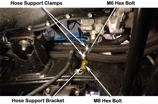
| 16 | Install the hose support bracket (Item 18) to the LHS chassis rail in the position shown and secure with the M8 SEMs hex bolt (Item 19).
Install the two hose support clamps (Item 17) over the hoses and secure to the hose support bracket (Item 18) with an M6 SEMs hex bolt (Item 20). |
 |
||||||||||||||||||||||||||||||||||||||||||||||||||||||||||||||||||||||||||||||||||||||||||||||||||||||||||||||||||||||||||||||||||||||||||||||||||||||||||||
| 17 | Install two hose support clamps (Items 17) over the hoses and secure with M6 SEMs hex bolt (Item 20), body washer (Item 22) and nyloc nut (Item 21). | 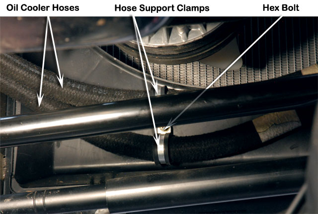 |
||||||||||||||||||||||||||||||||||||||||||||||||||||||||||||||||||||||||||||||||||||||||||||||||||||||||||||||||||||||||||||||||||||||||||||||||||||||||||||
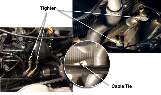
| 18 | Tighten the hose fittings at each end of the two oil cooler hoses.
Use a cable tie (Item 9) to retain the two hoses together as shown. |
 |
||||||||||||||||||||||||||||||||||||||||||||||||||||||||||||||||||||||||||||||||||||||||||||||||||||||||||||||||||||||||||||||||||||||||||||||||||||||||||||
| 19 | Reinstall the steering damper bracket to the RHS chassis rail. | 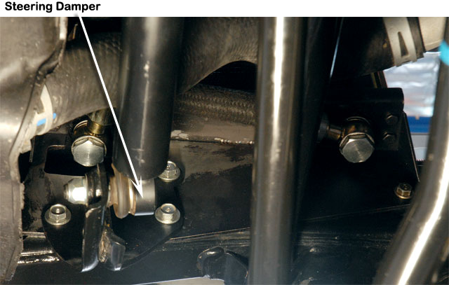 |
||||||||||||||||||||||||||||||||||||||||||||||||||||||||||||||||||||||||||||||||||||||||||||||||||||||||||||||||||||||||||||||||||||||||||||||||||||||||||||
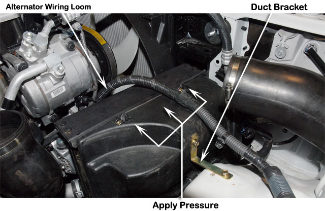
| 20 | Install the upper duct mounting bracket (Item 31). Apply light pressure on the duct to seal against the oil cooler assembly and retain with two M6 SEMs hex bolts (Item 24).
Route the alternator wiring loom over the oil cooler assembly and install the wiring to the alternator. |
 |
||||||||||||||||||||||||||||||||||||||||||||||||||||||||||||||||||||||||||||||||||||||||||||||||||||||||||||||||||||||||||||||||||||||||||||||||||||||||||||
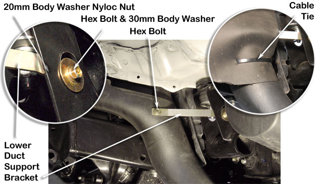
| 21 | Install the lower duct support bracket (Item 32) and secure to the duct (Item 30) with a M6 SEMs hex bolt (Item 24).
Secure the bracket to the chassis with a M6 SEMs hex bolt (Item 33), 30mm body washer (Item 34), 20mm body washer (Item 22) and M6 nyloc nut (Item 21). Reinstall the inner guard liner. Pierce a hole in the inner guard liner and install a cable tie (Item 9) to secure the liner to the duct (Item 30). |
 |
||||||||||||||||||||||||||||||||||||||||||||||||||||||||||||||||||||||||||||||||||||||||||||||||||||||||||||||||||||||||||||||||||||||||||||||||||||||||||||
| 22 | Reinstall the air cleaner assembly and secure with the original mounting hardware. | 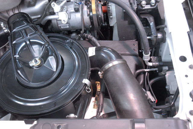 |
||||||||||||||||||||||||||||||||||||||||||||||||||||||||||||||||||||||||||||||||||||||||||||||||||||||||||||||||||||||||||||||||||||||||||||||||||||||||||||
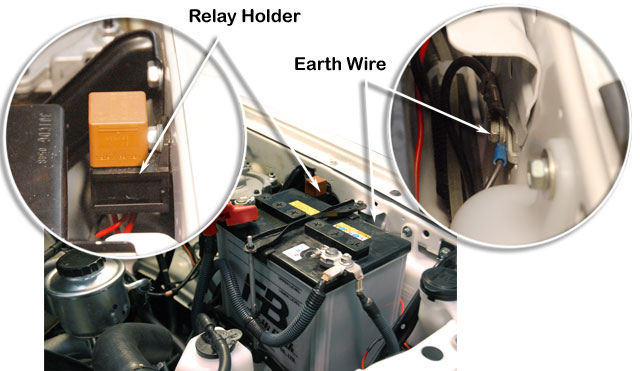
| 23 | Install the relay holder (Item 29) to the LHS inner guard in the position shown and retain with the original bolt.
Install the earth wire (Item 29) to the factory earth point on the LHS inner guard and retain with the original bolt. Route the wiring loom towards the front of the engine bay. |
 |
||||||||||||||||||||||||||||||||||||||||||||||||||||||||||||||||||||||||||||||||||||||||||||||||||||||||||||||||||||||||||||||||||||||||||||||||||||||||||||
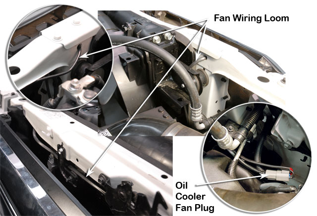
| 24 | Route the fan wiring loom (Item 29) through the radiator support panel from the LHS to the RHS of the engine bay.
Connect the wiring loom (Item 29) to the oil cooler fan plug. |
 |
||||||||||||||||||||||||||||||||||||||||||||||||||||||||||||||||||||||||||||||||||||||||||||||||||||||||||||||||||||||||||||||||||||||||||||||||||||||||||||
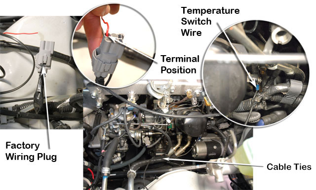
| 25 | Locate the factory wiring plug as shown and remove the rubber grommet seal from the terminal shown.
Insert the terminal from the fan wiring loom (Item 29) into the factory wiring plug in the position shown. Install the temperature switch wire from the fan wiring loom (Item 29) to the oil temperature switch on the oil filter/thermostat block (Item 15). Secure the temperature switch wire to the fuel hose with cable ties (Item 38). |
 |
||||||||||||||||||||||||||||||||||||||||||||||||||||||||||||||||||||||||||||||||||||||||||||||||||||||||||||||||||||||||||||||||||||||||||||||||||||||||||||
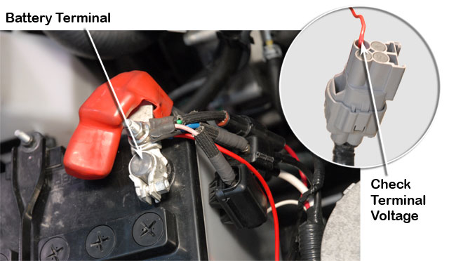
| 26 | Install the battery positive wire from the fan wiring loom (Item 29) to the positive battery terminal.
Reconnect the battery earth terminal. With ignition OFF, confirm zero voltage on the terminal shown. With ignition ON confirm +12V on the terminal shown. |
 |
||||||||||||||||||||||||||||||||||||||||||||||||||||||||||||||||||||||||||||||||||||||||||||||||||||||||||||||||||||||||||||||||||||||||||||||||||||||||||||
|
Completion of Installation
|
||||||||||||||||||||||||||||||||||||||||||||||||||||||||||||||||||||||||||||||||||||||||||||||||||||||||||||||||||||||||||||||||||||||||||||||||||||||||||||||